Study on the impact of optimal design of internal space layout of pre-assembled substation on the stability of equipment operation

Data publikacji: 17 mar 2025
Otrzymano: 21 paź 2024
Przyjęty: 07 lut 2025
DOI: https://doi.org/10.2478/amns-2025-0195
Słowa kluczowe
© 2025 Jingchao Guo et al., published by Sciendo
This work is licensed under the Creative Commons Attribution 4.0 International License.
In order to reduce power supply and distribution lines the end of road loss and improve the power supply power quality level, the requirements of high-voltage transmission lines as far as possible set up in the power load centre, or even take high-voltage into the house line directly into the load centre, concentrated to high-rise buildings and very large power consumption of industrial, mining, and enterprises for power supply [1-4]. Engineering applications, usually 100kVA ~ 1250kVA, 10kV / 0.4kV distribution transformer, placed in the power load power centre for centralized power supply, especially in small areas, there is a need to build a set of high-voltage receiving equipment, distribution transformers, and low-voltage distribution equipment for the integration of power supply and distribution facilities [5-8]. According to the centralised integration of power supply and distribution facilities, installation locations can be divided into indoor and outdoor two kinds, assembled in the manufacturing plant to become a finished product is commonly known as a combined substation. At the same time, in order to facilitate routine maintenance and improve the comprehensive service life of the distribution facilities, but also a combination of substations are installed in the “eye” or “Pin” box, which is called a box-type substation [9-12]. Pre-assembled box-type substation is a kind of high-voltage receiving switchgear, distribution transformer, and low-voltage distribution equipment in accordance with a certain wiring method to form an integrated factory prefabricated indoor and outdoor compact substation distribution equipment. It will be the introduction of high-voltage, transformer, and low-voltage power distribution and other functions organically combined [13-16]. The optimal design of the internal space layout of the pre-assembled substation has the advantages of strong set, high degree of integrated automation, small size, small area, high reliability of power supply, small line loss, short cycle of power delivery, strong adaptability to the environment, easy installation and maintenance, and beautiful appearance, etc., which can improve the stability of the operation of the equipment, and it plays a very important role in the plant and mining enterprises, residential communities, and rural substation projects [17-21].
This paper explores the internal space structure of pre-assembled substations, followed by structural optimisation based on the compact internal space layout structure, and the combination of photovoltaic power generation and intelligent pre-assembled substations in order to meet the requirements of the smart grid. Using the principle of photovoltaic power generation, the power supply of the pre-assembled substation is optimized using the compensation principle.The box structure of the pre-assembled substation is optimised in order to safeguard outdoor work and transport issues.The practicality of this paper’s method is investigated through simulation experiments on the transportation working conditions of intelligent pre-assembled substations, and tests on the operational stability effects of electrical equipment.
Pre-assembled substations, also known as box-type substations, are referred to as box variable substations. It is enough a kind of high-voltage switchgear, distribution transformers and low-voltage distribution devices, according to a certain wiring scheme into one of the factories prefabricated and after the type test of the rolls of equipment, that is, the high-voltage receiving, transformer, low-voltage power distribution and other functions organically combined.
The pre-assembled substation is different from a conventional civil substation. Its main features are:
pre-assembled substation in the manufacturing plant to complete the design, manufacture and installation, and complete its internal electrical wiring. Pre-assembled substation before leaving the factory to go through the required type test assessment. It has a series of advantages, such as strong integration, small size, less land, flexible site selection, strong adaptability to the environment, easy installation, safe and reliable operation, ability to improve power quality and reduce losses, short cycle of power delivery, and low investment and quick results.
Pre-assembled substations are generally used outdoors, and the requirements are more stringent, so it is necessary to solve many problems in the structure, such as low-voltage switchgear and high-voltage switchgear if the surface of the condensation will cause flashover discharge, so condensation should be prevented. Transformer heat will cause a drop in output, so to prevent heat. Substation shells exposed to the atmosphere are susceptible to corrosion candle, so to prevent corrosion alone. The natural ventilation of the substation can trap dust, which is detrimental to insulation, and therefore it should be protected against dust.Pre-assembled substations may have an internal fault arc, so it is important to prevent an explosion.
In short, the pre-assembled substation has a wide range of applications, suitable for urban public power distribution, residential neighbourhoods, high-rise buildings, and parks, but also for industrial and mining enterprises, oilfields and construction sites, etc., following the rise of civil substations after a brand new substation.
The common structure of the prefabricated substation is shown in Figure 1, and the internal spatial structure layout of the prefabricated substation can be divided into the “product” type arrangement and the “eye” type arrangement, which can be reasonably selected according to the geographical location and environmental restrictions. The layout of the word type is usually more convenient for wiring, so in actual use, the word arrangement is much more commonly used than the word type arrangement. However, the structure of the “pinzig” layout is relatively compact, especially when multiple transformers are arranged in the transformer room. The “pinzig” layout is more suitable for economic choice. Therefore, in the actual design, it is usually necessary to consider its cost and installation difficulty, and judge which layout to choose according to the actual situation.
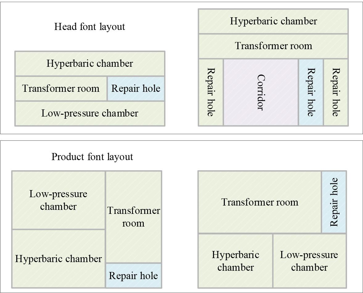
The commonly used structure of pre-installed substation
The optimal design of a prefabricated substation needs to consider heat dissipation, fire protection, grounding, maintenance, and transportation. The design of the substation box is also inseparable from the optimization of the internal space layout. Therefore, while considering the above problems of prefabricated substations, this paper optimizes the structure on the basis of compact, i.e., “zigzag” layout structure design, and carries out the intelligent exploration of prefabricated photovoltaic substations in order to meet the requirements of smart grids.
The traditional pre-assembled substation mainly has the following technical problems due to its structure.
Cannot solve the spear quality between sealing and ventilation. The axial fan is easy to stop working after a long period of operation, and the transformer room can not achieve the effect of heat dissipation. Unable to solve the load switch on the port (grid side), electricity can be replaced when the performance of the shock breaker or maintenance switch. Transformer oil level, gas, pressure relief, and other equipment are required to open the door during the charged interval for monitoring purposes, not to facilitate normal patrolling.
Pre-assembled substation ground area is large, foundation production costs, transport costs, transport difficulties, etc.
The load switch on the high-voltage side can only be operated manually, and it is impossible to realise the protection of the transformer, such as gas, over-temperature, over-pressure, etc., which is a hidden danger in operation. The high-voltage side does not have an obvious disconnection point, and replacing a single transformer requires cutting off multiple transformers on a single line, which impacts the normal power generation of the wind power plant. The Transformer Department needs to install backup fuse protection. Suppose the replacement of the fuse needs to open the box, a great waste of manpower and material resources.
In this paper, the design of an intelligent pre-assembled substation is the high-voltage switch electrical equipment and secondary intelligent equipment drain in the combination of a movable, insulated, anti-condensation, moisture-proof, rain-proof all-metal-sealed outdoor-type front of the body, with intelligent detection, protection, control, communication function of the pre-fabricated into a blue-condition electrical setup. Its control mode is switching station, main transformer and secondary energy switchgear composed of intelligent pre-assembled substation, which can achieve “four remote” (telemetry, telematics, remote control, remote control) intelligent functions and unattended operation management and maintenance mode.
Intelligent pre-installed substations are installed with comprehensive substation automation equipment according to the requirements on the basis of the original existing structure, and there is not much change in the shape structure and external dimensions. However, due to its internal microelectronic equipment to complete the intelligent task in a small space, it is easy to produce electromagnetic coupling with strong electrical equipment, so this microelectronic equipment and its power supply equipment require a strong anti-electromagnetic interference capability.
The intelligent pre-assembled substation system framework shown in Figure 2, automation monitoring, protection equipment is an important supporting equipment for an intelligent pre-assembled substation, divided into the main equipment protection equipment, transmission line protection equipment, safety, automation monitoring equipment and power system with communication protection equipment. The existing comprehensive automation complete sets of devices are also available, depending on the type of demand, to choose different sets of equipment. The secondary system of intelligent pre-assembled substation adopts the integrated automation of substation composed of microcomputer monitoring and protection devices, which can realise the functions of remote closing, remote splitting, hand and hand splitting, remote (hand) closing accelerated jumping and anti-jumping for the main substation’s high-voltage and low-voltage side circuit breakers. At the same time, it is equipped with differential, gas, and temperature protection for fixed-time overcurrent, electric current break, second harmonic braking, and ratio braking. When the main transformer adopts fuse protection, and the high-voltage side selects the load switch, the transformer automation protection device cancels the differential protection and adds high-voltage fuse phase-loss protection, i.e., when a certain phase of the fuse dissolves, it will cut off the load on the low-voltage side of the transformer and send out a fault signal to the dispatching system, so as to reduce the loss of the users.
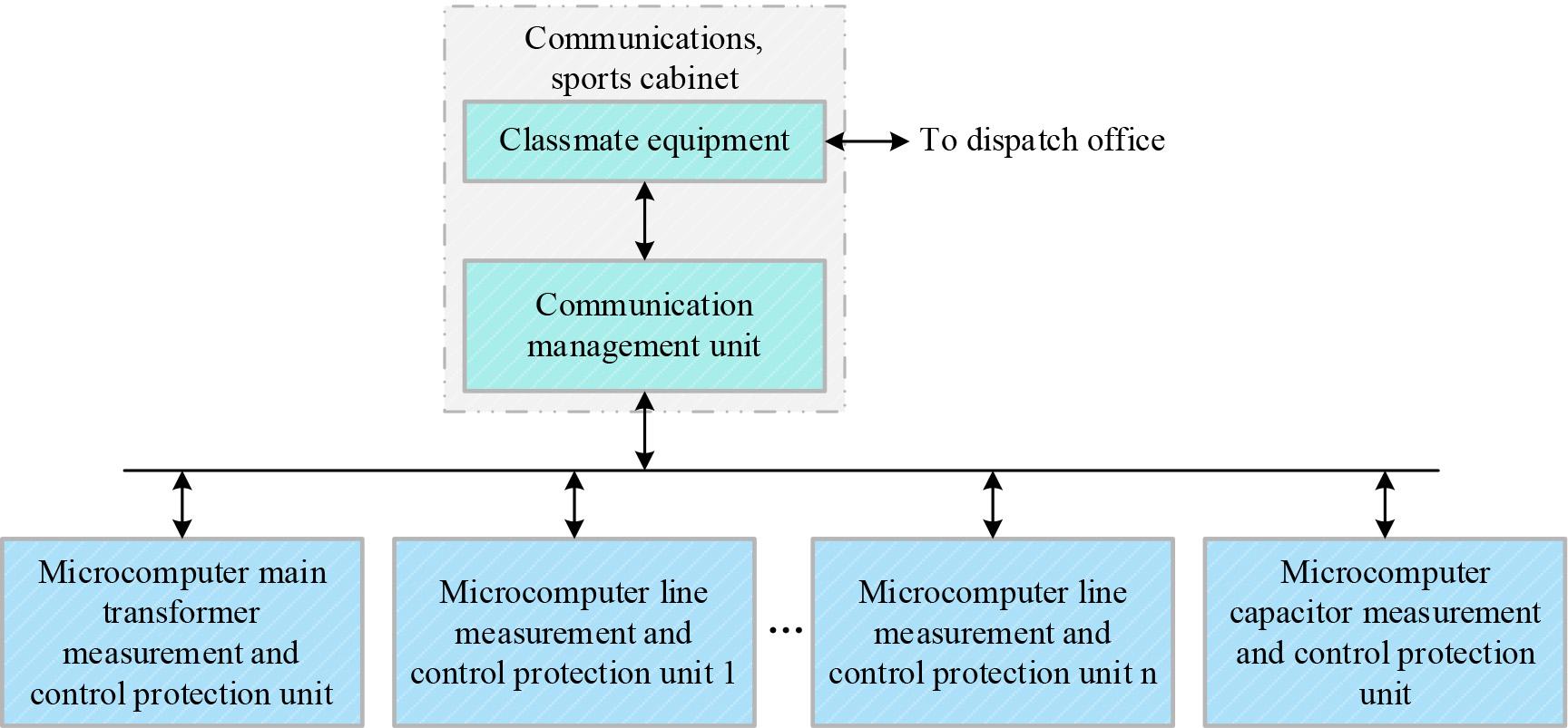
System framework for smart type pre-installed substation
Usually, people will install intelligent pre-assembled substation products in outdoor areas so that they can maintain a large distance from the distribution room, and for the voltage transformer, its output rated capacity is often not high enough, so that it will face numerous problems in actual use. To address these problems, this design does not use voltage transformers but instead uses solar power panels to achieve voltage power supply.The solar panels are installed on the outside of the intelligent box-type substation, and the energy collected by the solar panels is inverted to generate electricity for use by the substation products. In order to ensure the stability of the power supply, in addition to the power provided by the solar panels, a PT power supply is also installed so that when one side of the power supply fails, there is another side of the power supply as a backup.
In order to reduce losses, two methods are usually used in reactive power control: one is to reduce losses, and the other is to adjust the voltage. The principle of overall compensation means that when carrying out reactive power control, reactive power balancing is carried out in the whole network and also in subsections, and the two are combined to ensure that all sections from the generation side to the consumption side are fully covered. Compensatory measures should be implemented for zones with different loss ratios.For lines with different voltages, when carrying out reactive power control, the voltage should be adjusted or the losses should be reduced according to the actual situation.
This can be approximated by assuming that the natural power factor
The power loss of the system is:
Power loss can be minimised as long as the use of make |
In fixed photovoltaic cell arrangement, the bracket is fixed, the angle can not be adjusted according to the angle of solar radiation, and power generation is affected to a certain extent, but the bracket is simple, the cost is low, and the later maintenance cost is low. The fixed adjustable type is a fixed gear adjustable bracket. The tilt angle of the component can be manually adjusted.In the photovoltaic array, the choice of operation mode needs to take into account the reliability of operation, equipment prices, maintenance costs after completion, failure rate, power generation benefits, and other comprehensive factors. The amount of solar radiation received on the inclined plane, with the increase in the height angle of the inclined plane, shows an increase and then decreases to a certain maximum value of solar radiation corresponding to the angle of the inclined plane of the symmetrical pattern of change. This project uses the irregular shape of the hillland in order to avoid operation and maintenance difficulties.The comprehensive cost and actual situation of the site are examined in this paper regarding fixed array operations.
Engineering commonly used the following formula to calculate the total radiation on the inclined plane and choose the best inclination angle:
The feed-in tariff Ep of the PV power plant is calculated as follows:
Pre-assembled substations operate outdoors and face different environmental temperatures during the four seasons.The operation of electrical equipment requires working in a specific environmental temperature, which requires extreme temperatures outside.Pre-assembled substation boxes can have refrigeration, heat preservation, and other temperature regulation functions.The box structure of thermal insulation technology aims to achieve the functions of a key core technology.Thermal insulation technology is a multidisciplinary cross-cutting technology, which encompasses materials science, heat transfer, structural science, and other disciplines of technology.Through the integration of these technologies, which can adjust the box structure and thermal insulation performance, substation equipment can operate in a variety of complex environments and remain stable.
Box heat insulation index of good and bad can usually be used to indicate the maximum temperature of the inner surface of the box, which intuitively reflects the structure of the thermal insulation quality. The purpose of thermal insulation is to ensure that the structure has a low internal surface temperature, which reduces thermal radiation to the human body and the amount of heat dissipated into the room. In addition, the internal surface temperature can be measured, although the measured value is used and the theoretically calculated value can not be equivalent but can be used to understand or reference the thermal insulation capacity of the box.
Thermal insulation can also be used directly to measure and evaluate the thermal inertia index (D value) of the box structure. The thermal inertia index characterizes the thermal stability of the enclosure structure. The greater the value of the thermal inertia index, the greater the attenuation of temperature fluctuations and the ability to delay. The indoor temperature fluctuations are small, the better the thermal stability.
The thermal inertness index
Thermal resistance
Define the thermal inertness number:
Thermal inertness indicator D:
In the case of a certain building material, the greater the thickness, the greater the thermal inertness index. Also in the case of a certain thickness, the greater the thermal inertness coefficient
And heat storage coefficient
The thermal inertness coefficient ε is determined by the dry density ρ, thermal conductivity λ and thermal specific heat capacity
Therefore, the box must meet the thermal performance requirements for the region affected by high radiant heat, in the radiation intensity is higher than 350
From manufacturing in the enterprise to the final use of the substation, because of the difference between the two sites, there will be a transport process in the middle, and the transport will need to go through the whole lifting or decomposition of the module lifting, equipment loading, equipment, land or sea transport, equipment loading and unloading and other processes. The focus of the mechanical strength of the box embodied in the box is the above process without deformation or damage. The strength and structure of the box is an important part of the reduction of transport losses, the box force calculation method is as follows.
The equilibrium equation for the force on the base frame when the box is moving in the direction of
The impact load generated by the steel chassis during the initial isostart operation is
Pre-assembled substation boxes contain heavy electrical equipment, and during transport to the installation site, the box will encounter bumpy roads and large dynamic loads, which may have an impact on its internal structural performance. Therefore, ensuring good transport conditions is an important prerequisite for the stable operation of intelligent pre-assembled substation equipment. This experiment first models the transport vehicle and road surface. Then, kinematic simulation is carried out using the virtual prototype for driving over speed bumps, expansion joints, and uneven road surfaces at high speeds.Finally, using finite element analysis, you can determine whether the box was damaged during the transport process based on the results of the structural performance analysis. The overall model of the transport vehicle is structurally simplified according to the real vehicle: the length of the whole vehicle is 15.41m, the width is 3.3m, the rolling friction coefficient between the tyres of the transport vehicle model and the ground is set to be 0.2, and the coefficient of friction when the tyres begin to slide in the initial stage is 0.8, which is considered to be greater compared with the rolling friction. The simulated working speeds are 5, 10 and 20km/h, i.e., normal speed, faster speed and maximum permissible speed.
Passing over the speed bump at normal speed is shown in Fig. 3. At normal speed, when the box transport vehicle traveled for 1 second, the speed was stable at 1.40m/s or less. In the process of passing the speed bump, the front wheel of the tractor passes at 2 seconds, the first wheel of the semi-trailer passes after 9 seconds, and the whole vehicle passes completely at 14 seconds. The maximum vertical acceleration is about 3.1m/s2, and the condition is a general impact.
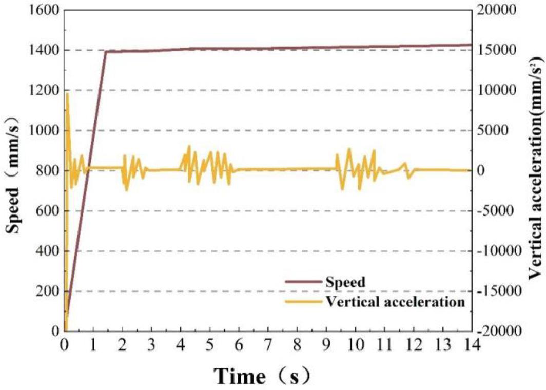
The speed of the deceleration belt is under normal velocity
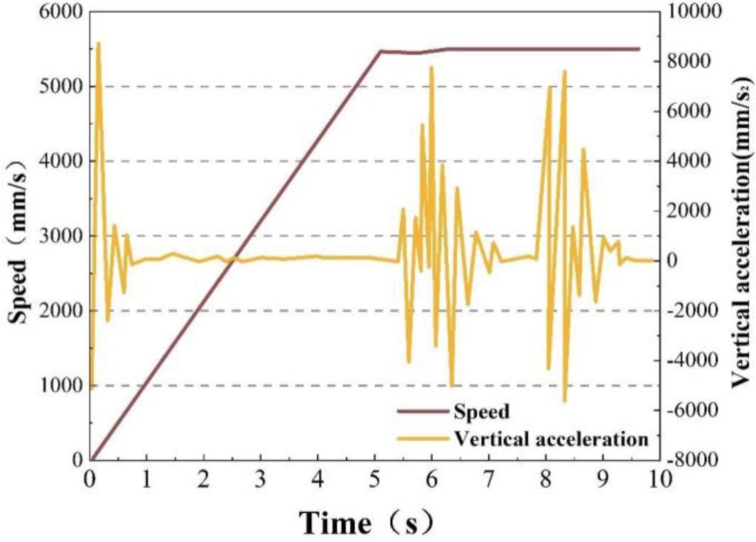
The situation of crossing the speed bump at a faster speed is shown in Fig. 4, and the kinematic simulation results show that the box transport vehicle reaches a smooth state when travelling at 2.3 seconds, with a speed of 2.68m/s up and down. After the box transport vehicle traveled for 2.9 seconds, the front wheels of the tractor hit the speed bump.At approximately 6.5 seconds, all the wheels of the tractor-trailer had passed the speed bump.The first wheels of the semi-trailer passed the speed bump in approximately 5 seconds, and the entire vehicle passed it completely in 12 seconds. The maximum vertical acceleration generated by the transport during the travelling period was 4.68 m/s2, and the working condition was a severe impact.

The speed of the deceleration band is fast
The maximum permissible speed over the speed bump is shown in Fig. 5. The speed of the transport vehicle is gradually stabilised at 5.45 m/s after 4.7 s. At about 5.1 s, the front wheels of the tractor-trailer arrive at the speed bump and are about to drive over it, and the first tyre of the semi-trailer passes over the speed bump at 7 s. Eventually, in 10 s, all the wheels are completely driven over the speed bump. During the whole process of the vehicle driving over the speed bump, the maximum vertical acceleration is about 7.98m/s2, and the working condition is maximum impact. By observing the acceleration curve, it is found that the acceleration of the vehicle is higher when traveling at a speed of 20km/h compared to when traveling at a lower speed through the speed bump. Therefore, the simulation result of 20km/h is selected as the input condition for finite element analysis to complete the structural stability analysis when verifying the transport box.
Maximum allowable speed down the speed belt
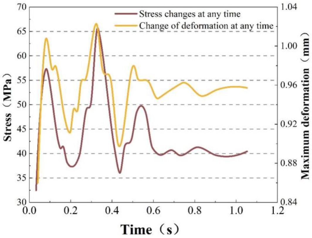
According to the results of kinematic analysis, the kinematic parameters of the pre-assembled substation box transport vehicle can be obtained when passing through the speed bump. In the finite element structural analysis, the maximum vertical acceleration value generated by the speed of 20km/h is taken as the input of the analysis condition, and the change of the situation of the pre-assembled substation box during transportation is shown in Fig. 6. The maximum stresses in the pre-assembled substation box are located at the top and bottom of the box. This is due to the fact that during transport, the pre-assembled substation box is often subjected to various external impact and vibration forces, which results in the appearance of stresses at the top and bottom. The stresses generated at different times are different, and the maximum stress occurs at 0.33 s, with a value of 66.53 MPa. The top is less stressful compared to the bottom, and there is no obvious part of the main structure with larger stresses, which indicates that the transport of the box body through the process of the speed bumps has a smaller impact on the structural stability of the box body equipment. Meanwhile, the top and bottom are the main locations where the pre-assembled substation box experiences the most deformation. The maximum deformation size of 1.017mm, the top relative to the bottom, the deformation is smaller, and the main structure does not have a significant deformation, further proving that the optimised box transport through the speed bumps in this paper on the deformation of the structure of the equipment has a smaller impact, which illustrates that this paper’s optimised design of the pre-assembled substation can effectively ensure the stability of the structure of the internal equipment in the transport process.
Changes in the case of pre-installed transformer substation in the transportation process
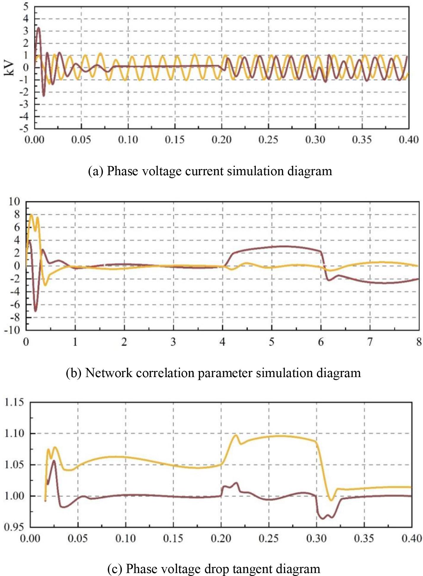
In order to further study the operating effect of the intelligent pre-assembled substation box optimally designed in this paper, simulink in MATLAB is used in this paper. The 10kV voltage generated by a three-phase programmable voltage source is simulated after the capacitor’s compensating operation.In this simulation circuit, the series resistor and branch circuit reactance are able to protect the entire grid. The role of the simulation circuit is also to be achieved by the capacitor. The main program can accept and judge the specific information of the voltage in each circuit and, according to the situation of each circuit, access or remove the capacitor and then achieve the overall control of the circuit.
The results of the simulation experiments are shown in Fig. 7 and Figs. (a)~(c) shows the current waveforms of the a-phase circuit, the Iq and Iqref reference currents (Iq in yellow and Iqref in brown), and the current waveforms before and after the cast-cutting of B1 (yellow) and B2 (brown), respectively. The currents detected in the a-phase circuit, Iq and Iqref, B1 and B2 capacitors are unstable before the cast-cut occurs.The currents become stable within 0.2 seconds of cutoff.The current in the circuit is very stable in the circuit after the implementation of the cast-cut in the optimised pre-loaded substation in this paper after the cast-cut command is issued. At this time, the a-phase voltage current, voltage signal ([-2.3, 3.2] kV), and 0.2 seconds after the occurrence of the cut command, the voltage is stable, the value is close to 1, and the operation of the grid is stable.
Simulation results
The comparison results of the main harmonic current values are shown in Table 1. The fundamental current value obtained from FFT analysis is 17A, which is 21% lower than before LC filtering, and the total harmonic current distortion rate THDi is 25%, which is 49% lower than before LC filtering.
The comparison of main harmonic current values
| Major harmonic times | Filter pre-current current value | Filter post-current current value | Reduction rate(%) |
| 5th | 8.09 | 0.918 | 90.1 |
| 7th | 3.56 | 0.757 | 81.2 |
| 11th | 3.19 | 0.34 | 92.8 |
| 13th | 2.22 | 0.23 | 94.8 |
| 175th | 2.04 | 0.199 | 85.9 |
The compensation effect of different pulse phase shift angles is shown in Table 2. Through the comparative analysis of different pulse phase shift angles, it can be seen that the active power before and after the compensation of different pulse phase shift angles increased 2022~17680P/W, the reactive power before and after the compensation of the reduction of 4055~16521Q/Var, and the power factor in the compensation of basically tends to tighten to 1. Overall, in view of the optimal compensation parameter, the dynamic reactive power compensation device compensation effect is remarkable and can successfully avoid the system overcompensation and undercompensation phenomenon, which further verifies the correct design of the compensation optimization parameters of this paper. Overall, under the optimal compensation parameters, the compensation effect of the dynamic reactive power compensation device is remarkable, and it can successfully avoid the phenomenon of over-compensation and under-compensation in the system, which further verifies the correctness of the compensation optimisation parameter design in this paper, and shows that the pre-assembled substation after the overall optimisation in this paper has the practicability, and the stability of the equipment current is stronger.
Compensation effect of different pulse shift Angle
| Pulse Angle | Active power(P/W) | Imaginary power(Q/Var) | power factor(ph) | |||
| Before | Later | Before | Later | Before | Later | |
| 55° | 9556 | 27236 | 16858 | 337 | 0.6685 | 0.99 |
| 60° | 8203 | 25878 | 15995 | 108 | 0.6311 | 0.99 |
| 65° | 7226 | 12913 | 15159 | 29 | 0.6045 | 1 |
| 70° | 4847 | 20326 | 13287 | 30 | 0.5152 | 1 |
| 75° | 3168 | 14925 | 11063 | 104 | 0.4455 | 1 |
| 80° | 1628 | 10229 | 7673 | 42 | 0.3725 | 1 |
| 85° | 631 | 2653 | 4072 | 17 | 0.3038 | 1 |
This study optimizes the design based on the internal space layout structure of the compact pre-assembled substation and combines photovoltaic power generation, intelligence, and a pre-assembled substation to construct an intelligent pre-assembled substation.
The maximum vertical acceleration of normal speed, faster speed and maximum permissible speed are about 3.1 m/s2, 4.68 m/s2 and 7.98 m/s2, respectively. When travelling at 20km/h, i.e., the maximum permissible speed, the acceleration of the vehicle is higher compared to the lower speed when travelling through the speed bump, so 20km/h is used as the input condition of the finite element analysis, and the analysis of the structural stability is more accurate and scientific.
In the finite element structural analysis, the maximum stress and deformation of the box of the pre-assembled substation occur at the top and bottom of the box. The maximum stress occurs in 0.33s, and the value is 66.53MPa. The top is smaller than the bottom, and there is no obvious part of the main structure with greater stress. The maximum deformation size is 1.15mm, the top is smaller than the bottom, and the main structure has no obvious deformation, which indicates that the internal space layout and box structure optimisation of the pre-assembled substation in this paper can effectively ensure the stability and safety of the internal equipment structure during transportation.
Different pulse phase shift angles before and after the active power compensation increased 2022~17680P/W, reactive power compensation before and after the reduction of 4055~16521Q/Var, and the power factor in the compensation basically tends to 1. Dynamic reactive power compensation device compensation effect is significant, but also explains that this paper optimised pre-assembled substation equipment current stability is stronger, with a good practical value.